
The trigger wire comes out from the cathode side of the xenon lamp. The coil generally uses positive triggering
In xenon lamp systems (particularly short-arc xenon lamps or photographic flash lamps), the trigger wire is connected to the cathode, and positive triggering is commonly used for reliable ignition and simplified circuit design. Below is a detailed explanation:
1. Why is the Trigger Wire Connected to the Cathode?
The cathode (typically a tungsten electrode that emits electrons) requires a stronger electric field to initiate gas ionization. The trigger wire is connected near the cathode (or integrated into its structure) for the following reasons:
-
Electric Field Concentration:
A high-voltage pulse (5–30 kV) applied near the cathode enhances electron emission, efficiently ionizing xenon gas to form a conductive path. -
Avoiding Anode Interference:
The anode (positive electrode) usually has a larger surface area, making direct triggering less effective. Cathode-side triggering ensures precise ionization control. -
Structural Simplicity:
Many xenon lamps position the trigger electrode (e.g., a metal ring or auxiliary wire) close to the cathode, simplifying wiring (e.g., short-arc lamps often have the cathode at the base).
2. What is "Positive Triggering"?
"Positive triggering" means the high-voltage pulse from the ignition coil is positive-polarity (instantaneous high voltage relative to ground). Its working principle:
-
Electron Acceleration:
A positive pulse attracts free electrons from the cathode, accelerating them into the gas to trigger avalanche ionization. -
Alignment with Main Power Supply:
During normal operation, the cathode (negative) emits electrons, and the positive trigger pulse aligns with this process, avoiding conflicts. -
Circuit Compatibility:
Most electronic triggers (e.g., SCR/IGBT-based) generate positive pulses more easily; negative triggering requires additional circuitry.
3. Typical Wiring (Positive Trigger + Cathode Connection)
Example (Short-Arc Xenon Lamp):
-
Trigger Coil:
-
Input: Low-voltage DC (e.g., 12V) or AC (e.g., 220V).
-
Output: Positive high-voltage pulse (e.g., +15 kV).
-
-
Lamp Connection:
-
Trigger wire links the coil’s HV (+) output to the cathode’s trigger electrode (or cathode lead).
-
Main power (–) connects to the cathode; (+) connects to the anode.
-
-
Operation Sequence:
-
Trigger phase: Positive pulse → cathode ionization → plasma channel formation.
-
Main power phase: Cathode emits electrons → anode collects them → stable arc.
-
Circuit Diagram:
Trigger Coil (+) → Trigger Wire → Lamp Cathode Trigger Main Power (–) → Lamp Cathode Main Power (+) → Lamp Anode Trigger Coil (GND) → Main Power (–) (Common Ground)
4. Positive vs. Negative Triggering
| Feature | Positive Triggering | Negative Triggering |
|---|---|---|
| Pulse Polarity | High voltage = positive (+) | High voltage = negative (–) |
| Ionization Efficiency | High (easier electron extraction) | Requires higher voltage |
| Circuit Complexity | Simple (SCR/IGBT compatible) | Needs additional circuitry |
| Applications | Photography, traffic signals | Special industrial lamps |
5. Key Notes
-
Polarity Matters: Reversing polarity may cause ignition failure.
-
Grounding: The trigger coil’s ground (GND) must connect to the main power (–) for a complete circuit.
-
Insulation: Cathode-side wiring must withstand high-voltage transients (e.g., silicone-insulated wires + ceramic isolators).
6. FAQs
-
Q: Can negative triggering be used instead?
A: Yes, but it requires a negative HV module and lamp compatibility. -
Q: What if the trigger wire has poor contact?
A: Weak pulses cause delayed ignition, flickering, or failure.
Summary
Connecting the trigger wire to the cathode with positive triggering optimizes ionization, simplifies circuitry, and ensures reliable ignition in professional xenon lamps (e.g., for photography or traffic systems). For device-specific analysis, provide the lamp/coil model or circuit diagram.
Trigger Coil in HVAC: The Essential Spark for Your Boiler's Ignition System
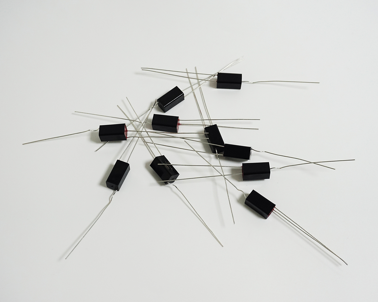
Trigger Coil
Related Article

Min. trigger voltage: 150V
Secondary trigger voltage: 6KV (or higher)
At first glance, these numbers seem contradictory. Why would the same lamp require both 150V and 6KV to trigger? The answer lies in how a flash system works

But what if the datasheet only gives a single nominal value for the primary? This article explains the minimum reliable voltage, maximum continuous voltage, and peak limits for trigger coils used with all xenon flash lamps.
